What are iClickers?
iClickers are used in a lot of colleges in order to conduct quizzes and take attendance. The whole ecosystem operates as follows:
-
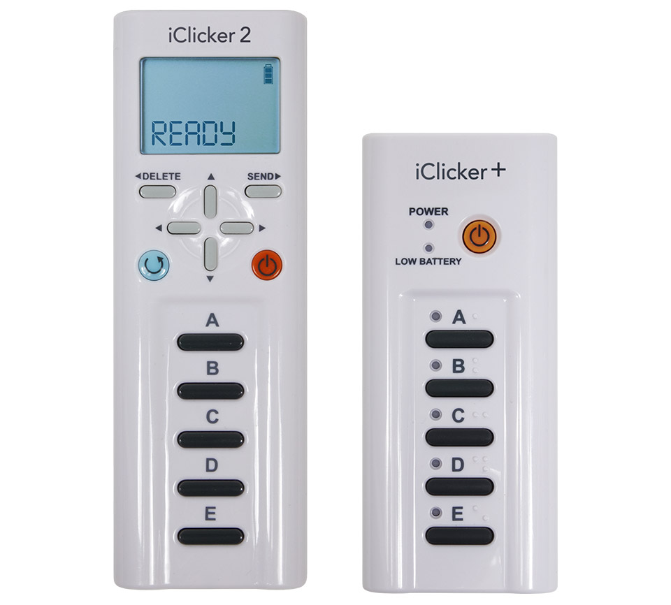
Each student buys an iClicker device. They’ve got some buttons on them to respond to multiple choice questions.
-
They enter the unique ID on the back of the device into their school database.
-
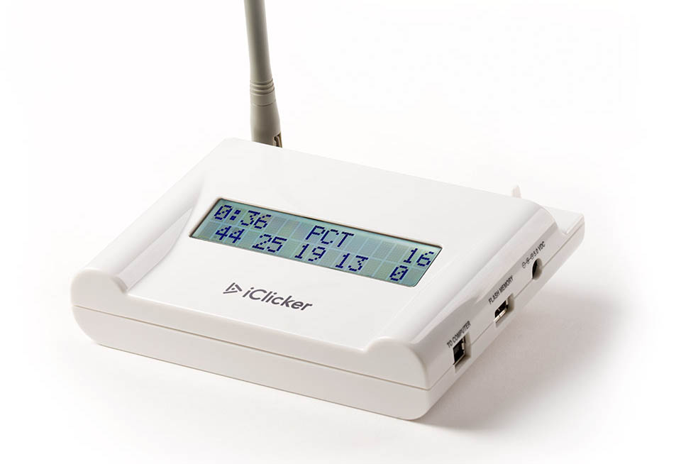
Each class is equipped with a base station that connects to the instructor’s computer via USB.
 With iClicker’s software, they can
conduct quizzes and export the answers for automatic grading.
With iClicker’s software, they can
conduct quizzes and export the answers for automatic grading.
State of the art of iClicker reverse engineering
A significant amount of work has been done as far as figuring out how the student owned remotes work. The seminal work in this area is contained in this fantastic paper conducted by some students at the University of British Columbia where they dumped out the firmware of the remote. Some key contributions they made were figuring out the exact radio transceiver used in the device as well as the obfuscation scheme used in the transmission of the IDs.
Following up to this, some students at Cornell started off a project called iSkipper where they attempted to create an open source alternative to the iClicker. By using logic analyzers and dumping out the raw communications using a software defined radio, they were able to piece together the protocol that the remotes use to send their answers over the air. They wrote their own implementation of an iClicker that can be run on an Arduino with just a 900MHz radio transceiver.
While the iSkipper project has managed to figure out most of the iClicker protocol, one missing piece is the communication from the base station back to the remotes. Upon pressing a button, the base station sends back an acknowledgement packet to indicate that the answer has been accepted. In addition, the base station can also send a welcome message to the remotes to indicate what class is currently in progress.
In order to figure out this last missing piece of the iClicker puzzle, I set out to reverse engineer the receiver.
Acquiring the firmware
The first part of reverse engineering the base station would be to obtain the firmware that runs on it. Since I didn’t own a base station and didn’t want to buy one (you can get them for anywhere between $50-$100 on eBay), I had to figure out an alternative approach to acquiring the firmware.
Searching for iClicker base station firmware led me to the “iClicker Base Firmware Utility” on the iClicker downloads page. This software claimed to be able to update the firmware on a base station so it seemed like a natural target. I initially guessed that they would package the updated firmware with the executable but searching around in the distributed files I couldn’t locate any firmware files. Next up I ended up starting the executable.
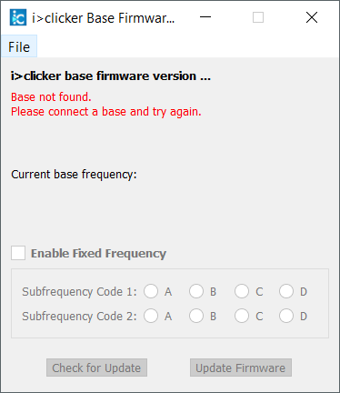
“Check for Update”, interesting. This was a massive hint that the updates were most likely downloaded over the internet. Thus, I cracked open the executable in IDA and searched away for interesting URLs.
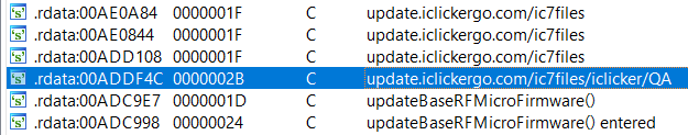
Aha! http://update.iclickergo.com/ic7files/iclicker/QA/.
Opening up this URL in a browser, I found that most of the files were updates the firmware utility itself, but there were two very interesting files:
- update_v0602.txt
- U_BASEU_V0058.txt
Here is a chunk of update_v0602.txt:
:100000000C942B010C9474120C9499120C94000013
:100010000C9400000C9400000C9400000C94000060
:100020000C9400000C942B130C9400000C94501BA7
:100030000C9400000C946D1B0C9400000C940000B8
:100040000C9400000C9400000C9400000C94000030
:100050000C94000000002110422063308440A55021
For those unfamiliar, this an Intel HEX file, Getting into a binary format was as simple as:
objcopy -I ihex update_v0602.txt -O binary firmware.bin
and with that, I had the firmware on my hands without having to install a JTAG interface or an AVR programmer into a base station.
Reverse engineering the firmware
Alright so next up we gotta disassemble the firmware. I strongly suspected that there was some Atmel chip inside the base station, just like the remote. Atmel makes some very popular programmable microcontrollers, a lot of embedded systems, IoT devices and the Arduino platform use Atmel chips.
Luckily IDA supports disassembling AVR, the architecture used by these microcontrollers. So I cracked the firmware open in IDA and went to hunt down the code that generates the acknowledgement packets.
Take the next section with a heavy grain of salt, this was my first time reverse engineering embedded software and it was very much new and uncharted territory for me. If I made any glaring mistakes, please feel free to reach out and I’ll try to amend them :)
ID Decoding
There was a lot of code and I wasn’t exactly familiar with AVR so in order to get my bearings, I set out to find a known piece of the protocol: the scrambling and de-scrambling routine for the iClicker remote ID. The iSkipper project had already figured out the algorithm to do this:
void iClickerEmulator::decodeId(uint8_t *id, uint8_t *ret) {
    ret[0] = (id[0] >> 3) | ((id[2] & 0x1) << 5) | ((id[1] & 0x1) << 6) | ((id[0] & 0x4) << 5);
    ret[1] = ((id[0] & 0x1) << 7) | (id[1] >> 1) | (id[2] >> 7);
    ret[2] = ((id[2] & 0x7c) << 1) | (id[3] >> 5);
    ret[3] = ret[0]^ret[1]^ret[2];
}
So a good place to start would be finding functions that do a lot of bit shifting. Searching for “lsr” (Logical Shift Right), I found a peculiar function:
loc_375a:
  lsr     r30
  lsr     r30
  lsr     r30
  ret
In AVR, the lsr opcode shifts its argument register right by 1 bit, this looked
an awful lot like the initial part of the decoding algorithm so I followed to
the callers of this right_shift_3 function.
There were some cool tricks that the compiler used in this area, for example in
order to shift right by 7, it didn’t emit 7 lsr instructions. Instead, the
sequence of instructions was
swap    r30
andi    r30, 0xF
lsr     r30
lsr     r30
lsr     r30
The swap instruction swaps the two nibbles of the byte, so the higher order
4 bites get swapped with the lower order 4 bits. Performing an and with 0xF = 0b1111
after this essentially does the same thing as shifting right by 4.
While this approach led me to the function that decodes the ID, the rest of the calling logic was not particularly easy to follow. I needed to find more landmarks in the code to figure out what was going on.
Radio SPI Interface
As mentioned in the introduction, previous reverse-engineers had already figured out what radio chip was used in the clicker, namely the Semtech XE1203F.
Consulting the datasheets for the IC, we can see that it uses a 3-wire SPI (Serial Peripheral Interface) based protocol in order to configure the radio chip. The next logical step was to look at an SPI tutorial for AVR microcontrollers, I found a great one here with the following code sample:
SPI_Send:
ldi r16,0xAA
out SPDR,r16         ; Initiate data transfer.

Wait:
sbis SPSR,SPIF       ; Wait for transmission to complete.
rjmp Wait
in SPDR,r16	         ; The received data is placed in r16.
Perfect, so we have to look up usages of the SPDR register within the
firmware. There is only one place that used this register, so I labelled the
function as read_write_from_SPI. It reads one argument stored at (Y+1) and
then writes it out the SPI port.
ROM:1393 read_write_from_SPI:                    ; CODE XREF: read_write_two_bytes_SPI
ROM:1393                 st      -Y, r16         ; Spill register r16
ROM:1394                 cli                     ; Disable interrupts
ROM:1395                 ldd     r30, Y+1
ROM:1396                 out     SPDR, r30       ; SPI Data Register
ROM:1397
ROM:1397 loc_1397:                               ; CODE XREF: read_write_from_SPI+7
ROM:1397                 in      r30, SPSR       ; SPI Status Register
ROM:1398                 andi    r30, 0x80
ROM:1399                 cpi     r30, 0x80
ROM:139A                 brne    loc_1397
Here is one of the usages of the SPI writing function:
ROM:082A                 ldi     r30, 0xF
ROM:082B                 ldi     r31, 0x8A
ROM:082C                 st      -Y, r31
ROM:082D                 st      -Y, r30
ROM:082E                 call    read_write_two_bytes_SPI
ROM:0830                 ldi     r30, 0xA0
ROM:0831                 ldi     r31, 0x8B
ROM:0832                 st      -Y, r31
ROM:0833                 st      -Y, r30
ROM:0834                 call    read_write_two_bytes_SPI
Now if we consult with the XE1203F’s documentation, it mentions the following:
The timing diagram of a write sequence is illustrated in Figure 12 below. The sequence is initiated when a Start condition is detected, defined by the SI signal being set to “0” during one period of SCK. The next bit is a read/write (R/W) bit which should be “0” to indicate a write operation. The next 5 bits contain the address of the configuration/status registers A[4:0] to be accessed, MSB first (see 5.2). Then, the next 8 bits contain the data to be written into the register. The sequence ends with 2 stop bits set to “1”.
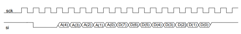
Okay cool, now if we take a closer look at the bytes being written out on the SPI interface as binary, we see the following:
0x8A          0xF

1000 1010   0000 1111
Compare this against the timing diagram from the datasheet above, looks fairly similar! If we plot it out and label the bits, we see the following:

Great, so this is code that is writing a value to a configuration register in
the radio chip. Notably it’s writing the value 0xF to the register at
address 0x01010. I confirmed this theory by decoding a few more SPI writes.
| Register | Value | Description |
|---|---|---|
| 0x01010 | 0x0F | Frequency Adjustment MSB |
| 0x01011 | 0xA0 | Frequency Adjustment LSB |
| 0x00010 | 0x1F | Frequency Band 902–928 MHz |
Following the formula in the datasheet, we can see that the frequency will be the base frequency plus 500 times the frequency adjustment registers interpreted as a 16 bit two’s compliment number.
Frequency Base = 915 Mhz
Frequency Adjustment = 0x0FA0 = 4000

Final Frequency = (915 Mhz) + (4000 * 500 Hz)
                = 917 Mhz
and if we check this against the first paper linked above, we can confirm that
they experimentally figured out the default AA channel operates at 917.0 MHz.
Great, this discovery lets us figure out exactly what parameters the radio module is using and helped find the portion of the code responsible for changing frequencies.
Radio Data IO
So the SPI protocol is how the radio module is configured, but looking at the
data sheet we can see that there is a separate DATAIN and DATA port used to
read and write actual radio packets. My first intuition was that the firmware might
be making use of the AVR USART (Universal Synchronous/Asynchronous Receiver/Transmitter)
feature to exchange data with the radio chip.
However, after looking at the interrupt handlers for USART_RXC and USART_TXC
which correspond to when a byte is sent or received by the USART module, it
seemed clear that this is actually how the base station communicates with the
instructor’s computer and NOT where radio messages were read/sent.
Within AVR, IO is primarily done using the in and out instructions. The only
interesting traces I could find for the in instruction was in the INT1
interrupt handler which corresponds to a configurable external interrupt handler.
The following is psuedo-C like code that corresponds to the handler:
int8_t radio_bytes_read = 0;

int8_t radio_bits_to_read = 8;
int8_t radio_bytes_to_read = n;

extern int8_t* radio_bytes;

void INT1() {
    while (radio_bytes_to_read > 0) {
        while (radio_bits_to_read > 0) {
            int8_t current_byte = radio_bytes[radio_bytes_read];

            if (PIND_5 is high) {
                current_byte |= 1;
            }
            current_byte = current_byte << 1;

            radio_bytes[radio_bytes_read] = current_byte;
            radio_bits_to_read--;
        }
        radio_bytes_to_read--;
        radio_bits_to_read = 8;
    }
}
And bingo, now that we know where radio_bytes array is in memory, we can
look at cross references to it to find the code that processes packets sent
over the radio.
Dynamic analysis
After a large portion of just statically analyzing the disassembled code, I
decided to use the fantastic avrsim
project that allows you to run avr binaries and even attach gdb to it.
I took the example code in examples/board_simduino/simduino.c and
customized it to my needs. The first most obvious change to make is to change
the MMCU to atmega16.
Next up was setting the appropriate bit and raising the external interrupts to emulate the radio module receiving bytes.
void send_byte(unsigned char b, avr_irq_t* radio_in, avr_extint_t* extint, avr_t* avr) {
    for (int i = 7; i >= 0; i--) {
        for (int j = 0; j < 200000; j++) {
            avr_run(avr);
        }

        int bit = (b >> i) & 1;
        printf("Writing bit %d\n", bit);
        avr_raise_irq(radio_in, bit);
        avr_raise_interrupt(avr, &extint->eint[1].vector);
    }
}

int main(int argc, char** argv) {
    ...
    int interrupted = 0;

    while (1) {
        int state = avr_run(avr);
        if ( state == cpu_Done || state == cpu_Crashed) {
            break;
        }

        // divide by 2 to get "word" addresses like IDA uses
        unsigned int curr_pc = avr->pc / 2;
        if (curr_pc == 0x18E && !interrupted) {
            // Perform an INT0 interrupt
            avr_raise_interrupt(avr, &extint->eint[0].vector);
            printf("Raising AVR INT0 interrupt\n");

            // Raw ID = 0xA2 0x46 0x53 0xB7
            // My encoded ID = 0x14 0x8C 0x29 0x70
            send_byte(0x14, radio_in, extint, avr);
            send_byte(0x8C, radio_in, extint, avr);
            send_byte(0x29, radio_in, extint, avr);
            // Sending an answer of 'B' (0x05)
            unsigned char last_id = 0x70;
            last_id &= 0xF0;
            last_id |= 0x05;
            send_byte(last_id, radio_in, extint, avr);

            // compute the checksum
            unsigned char checksum = 0x14 + 0x8C + 0x29 + last_id;
            send_byte(checksum, radio_in, extint, avr);

            interrupted = 1;
        }
    }
}
Protocol Findings
Hopefully the last section gives you some insight on what the reverse engineering process was like, not too harp on it too much, let’s move on to the actual findings in terms of the radio protocol:
Welcome ping packet
The base station sends out this packet on regular intervals (every few seconds), it contains the welcome message as shown on the iClicker like this:
as well as the question mode being used, which can either be the standard A/B/C/D/E multiple choice mode, numeric alphanumeric or a sequence of questions.
Packet details
| Byte | Description |
|---|---|
| 0-5 | Fixed header (Radio sync bytes)0x55 0x55 0x55 0x36 0x36 0x36 |
| 6-13 | Welcome message (note this is not ascii, see below) |
| 14 | Mode byte 1 |
| 15-16 | Number of questions (for multiple question modes) |
| 17 | Mode byte 2 |
| 18 | Checksum (sum of bytes 6-17) |
The mode bytes are as follows:
| Mode | Mode Byte 1 | Mode Byte 2 |
|---|---|---|
| Multiple Choice | 0x92 | 0x62 |
| Numeric Mode | 0x93 | 0x63 |
| Alphanumeric Mode | 0x9B | 0x6B |
| Multiple Numeric | 0x94 | 0x64 |
| Multiple Alphanumeric | 0x9C | 0x6C |
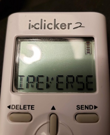
Here are some examples of a welcome packets.
This causes the iClicker to show IREVERSE on screen and puts it in the
multiple choice mode.
0    1    2    3    4    5    6    7    8    9    10   11   12   13   14   15   16   17   18
0x55 0x55 0x55 0x36 0x36 0x36 0x93 0x9C 0x8F 0xA0 0x8F 0x9C 0x9D 0x8F 0x92 0xAA 0xAA 0x62 0xFD
 ^-------------------------^  ^---------- Welcome Message ----------^  ^   ^-------^  ^    ^
  Header/Radio sync bytes     'I'  'R'  'E'  'V'  'E'  'R'  'S'  'E'   │    Useless   |  Checksum
                                                                       │              |
                                                      Question Mode (Multiple Choice) ┙
This causes the iClicker to show 2+2=5 on screen and allows 8 questions to be
answered in alphanumeric mode.
0    1    2    3    4    5    6    7    8    9    10   11   12   13   14   15   16   17   18
0x55 0x55 0x55 0x36 0x36 0x36 0x82 0xA6 0x82 0xA7 0x85 0x00 0x00 0x00 0x9C 0x08 0x00 0x6C 0xE6
 ^-------------------------^  ^---------- Welcome Message ----------^  ^   ^-------^  ^    ^
  Header/Radio sync bytes     '2'  '+'  '2'  '='  '5'  ' '  ' '  ' '   │  8 in little |  Checksum
                                                                       │    endian    |
                                                                       |              |
                                                Question Mode (Multiple Alphanumeric) ┙
Text encoding
As mentioned earlier, the welcome message isn’t a normal encoding like ASCII, it seems custom rolled.
-
1to9are from0x81to0x89. -
0is represented by0x8A. -
Astarts at0x8Band goes up sequentially like ASCII. -
-is0xA5. -
+is0xA6. -
=is0xA7. -
?is0xA8. -
_is0xA9. -
Any other bytes will show a blank.
Multiple choice answer ACK packet
Sent to acknowledge an answer for a multiple choice question. These involve
calculations on the encoded iClicker id, which I will refer to as an array
called encodedId.
Accepted
(Shows a tick on the iClicker screen)
| Bytes | Description |
|---|---|
| 0-2 | Fixed header (Radio sync bytes)0x55 0x55 0x55 |
| 3 | Byte 0 of the encoded iClicker ID (encodedId[0]) |
| 4 | Byte 1 of the encoded iClicker ID (encodedId[1]) |
| 5 | Bitwise negation of byte 2 of the ID (~encodedId[2]) |
| 6 | (encodedId[3] & 0xF0) | 0x02 |
| 7 | Constant 0x22 |
Closed
(Shows closed on the iClicker screen)
| Bytes | Description |
|---|---|
| 0-2 | Fixed header (Radio sync bytes)0x55 0x55 0x55 |
| 3 | Byte 0 of the encoded iClicker ID (encodedId[0]) |
| 4 | Byte 1 of the encoded iClicker ID (encodedId[1]) |
| 5 | Bitwise negation of byte 2 of the ID (~encodedId[2]) |
| 6 | (encodedId[3] & 0xF0) | 0x06 |
| 7 | Constant 0x66 |
Example
My iClicker ID is A24653B7, which encodes to 0x14 0x8C 0x29 0x75 when
answering B.
Let’s calculate the bitwise negation of my encodedId[2]:
0x29 = 0b00101001
    ~= 0b11010110 = 0xD6
Thus, a positive acknowledgement packet for this answer would be:
0x55 0x55 0x55 0x14 0x8C 0xD6 0x72 0x22
And a negative acknowledgement packet would be:
0x55 0x55 0x55 0x14 0x8C 0xD6 0x76 0x66
Side note: I haven’t documented the ACK packets for other question modes since I figured there’s not a lot of interest for those, please let me know if you’d like to see those.
Conclusion
This was my first real project reverse engineering a large real-world project, especially so in the embedded space. Compared to reverse engineering x86 a bigger chunk of time was spent reading datasheets for the hardware components, especially the Atmel processor. The lack of strings, system calls etc also make it a lot harder to orient yourself and find your way around the code.
I’ve posted my IDA database and a text dump of the firmware on Github. Feel free to reach out to me if you have any questions.